Chipper canters and chipper canter lines
The first saline machine is usually a chipper canter. The chipper canter can be seen as a basic element of a modern sawline.

Chipper canter works as follows:
- Two opposite sides of a log or a cant is worked so that you get timber with sawn surfaces.
- The surfaces created by the chipper canter have an important role because they are used as the guiding surfaces by the subsequent main machines. This ensures optimised sawing and produces timber with accurate dimensions.
- By working the outer surfaces of the log directly into chips (a valuable raw material in the pulp industry), you avoid any need for difficult surface treatment and thus make the sawing and edging process smoother and faster.
- The cutting speed of the chipper canter blades is nearly always frequency convertercontrolled, which allows for the chip length to be adjusted so that it remains the same regardless of the speed of the sawline.
- The feeding speed of a chipper canter can be 30–220m/min so it does not limit the feeding speed of other sawing machines.
The most common chipper canter blade construction is where the chipper blades are attached to the lateral surface of a steel conic frustum and with a surface-finishing circular blade on top.
The circular blade can:
- ‘cut first’, meaning that its diameter is larger than that of the chipping conic frustum. In this case, the circular saw works a groove into the log while the chipper blade behind it works the leftover material into chips.
- ‘cut second’; the outer surface is chipped first and then the circular saw simply smooths out the surface of the cant or spar into a sawn surface.
The thickness of the circular blade is typically 4–6mm. This means that the proportion of sawdust generated can, depending on the positioning of the blades, be up to 30–40 percent of the chipped surface section.
If you want to minimise the amount of sawdust, the circular saw can be replaced by chipper blades placed on top of the conic frustum. In this case, as with when the circular blade ‘cuts second’, the risk is that there may be checks on the trunk surface, especially around knots, that penetrate the wood.
However, the latter method is the common option in markets where the price of sawdust is low, the raw material from planted/cultivated forests shrinks a lot when drying, or where all timber is planed before being sent to the end user.
The chipper canter reducer head models:
- straight,
- grooved or
- spiral conic frustum or
- combination of these
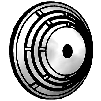

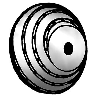
Blade templates of chipper canters. Source: Sipi M. (2002), © Antti Saikkonen
The number of blades in a straight or grooved structure is between three and eight. The straight blade plates reach from the reducer head’s centre plate to the frustum’s surface.
With a grooved reducer head, the blade plate, which runs the length of the entire reducer head, is divided into smaller segments. This way the blade width can be used to regulate the chip length.
The spiral frustum has dozens of smaller blades positioned in a spiral. With the first two versions, cutting is carried out against the grain, but with the spiral version the chipper blade’s main edge goes along the grain.
The chipper blades are blade plates or ‘claws’ that can be sharpened. However, disposable hard metal blades are also available. The use of disposable blades usually requires special solutions for knife holders and washers as well.

Pulp chip dimension
Good pulp chips should be around 20–25mm in length and width, with a thickness below 8 mm. Some pulp mills prefer a slightly longer chip in their process. At the sawmill, this can be achieved by increasing the chip thickness so that it exceeds 8 mm.
The length of chip produced by a chipper canter is determined by the feeding speed of the logs and cants, the rotation speed of the reducer head and the number of cutting blades.
L=1000 Å~ v ÷ (z Å~ n)
L = chip length [mm]
v = feeding speed of log/cant [m/min]
z = number of cutting blades on reducer head
n = rotation speed of reducer head [1/min]
Simple sawline constructions
In the simplest sawline construction,
- The log is first worked by the chipper canter, then
- returned on a conveyor in front of the chipper canter and
- worked into a spar during a second run.
If the chipper canter’s reducer head calibration device enables the blade position to be adjusted during working, it is possible to produce tapered construction product for the Egyptian market called “Egyptian Filleries” or “Egyptian Baulks”.
The next and more efficient sawline solution is to use a cant turner that tips the can’t 90 degrees, and a second chipper canter. If a ripsaw is added at the end of this line, you have a sawline that can efficiently saw small-dimensioned trunks into small section like two 44 x 100mm timber.
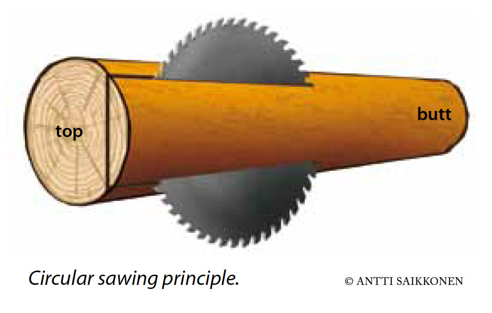
Circular saws and circular sawlines
Circular saws are increasingly being used to saw logs and cants into boards and centre cut timber.
Previously, the majority of sawmill equipment consisted of single-axis circular saws that had blade guides with water emulsion cooling. In recent years, many sawmills have moved on to guideless two-axis versions.
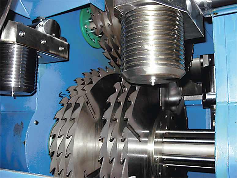
Typically, circular saw technology is used as a resaw machine. © Heinolan Sahakoneet Oy
The reasons behind the growing popularity of two-axis circular saws include:
- accuracy (S <= 0.3mm),
- wide feeding speed range (30–220m/min),
- good sawn surface quality,
- durable blades,§
- the option of running the saw without cooling water or additional guide plates.
On the other hand, saws with guides are still popular in the North American market where they are used, for example, as resaws as they can hold over ten blades on a single axis. The blade, which is the central element of the circular saw, is usually made of alloy steel while the teeth are made of hard metal. Normal maintenance of circular blades includes levelling, tensioning, replacement of teeth if necessary and sharpening.
Main properties:
- The same blades can be used for up to two work shifts or around 15,000 logs/cants before the blades need to be replaced when used on modern sawing machines.
- Replacing blades is a simple procedure and usually lasts only around 15 minutes.
- The blades normally come in a standard size, depending on the technical solutions used in a particular machine, and whether the machine is designed for logs, cants or spars.
- The blade diameter is usually 400–600 mm.
- The blade diameter is usually 400–600 mm. The thickness of the blade body is determined by the grade of the log to be sawn and the height of the cant. Thinner blade bodies can be used with smaller logs and lower cant. This allows you to make use of the better lateral support provided by bigger blade flanges.
- In order to change the blade positioning, a fixed blade pack is assembled on a steel axis using washers.
- The blades’ position on the axis can be adjusted, for example, by using nested axes, guide bars or changing the position of the actual machine.
- In systems with changing blade positions, the linear movement of the blades is created by backfeeding hydraulic or electric servos that receive their settings from the blade positioning support system of the line control system.
- In optimising solutions, the positioning can even be altered for each log or cant. The support system is normally used to fix or adjust blade positions, if required.
- The blade axes are turned by an electric motor or belt drive. The motor power is typically around 75–250kW, and a reduced voltage starter or frequency converter is usually included.
[arve url=”https://www.youtube.com/watch?v=_i-QUu7fZyk”]
Hewsawing and hewsawing lines

© Veisto Oy
A video from Keitele Timber’s Kemijärvi sawmill, where the sawing machine is HewSaw R200 1.1. V1. The video shows the sawing process from log sorting to sawn timber. Sawsets and the sawing machinery action is shown as an animation. (Duration 5:35)
[arve url=”https://www.youtube.com/watch?v=MWI6Gn1ggV8″]
A sawing method developed by the Finnish company Veisto Oy has become known as hewsawing. In this method, the log is chipped, sawn and edged into a finished timber by one machine.
- In the first stage of the method, four sides of the log are chipped.
- The cant is then sawn using circular blades.
- After this, the sideboards are either edged using a separate edging unit after they have been resawn, using a chipper edger situated on a circular blade axis, or using a combination of these. This will produce two side boards from two sides of the cant.
The hewsaw curve saws the log in a manner that delivers an optimal yield. The log is positioned by a 1- or 2-rotor log rotator so that the curved log travels towards the saw in the correct position. A separate curve feeder may also be used.
The hewsaw was developed for sawing logs with a top diameter of 70–380 mm. The feeding speed can vary between 60 and 200m/min.
Hewsawing produces a good yield, good surface quality and chips that meet the relevant quality requirements.
Bandsaws and bandsaw lines

The principle of a bandsaw. © Antti Saikkonen
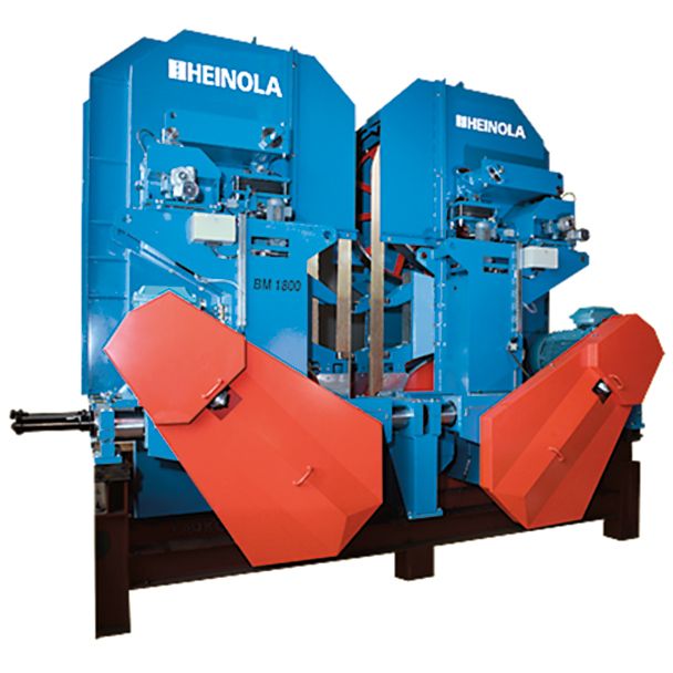
The bandsaw unit. Heinola Sawmill Machinery Inc.
A bandsaw has a narrow saw blade that runs around two equal-sized wheels at an even pace while cutting the fed wood into the specified dimension.
[arve url=”https://www.youtube.com/watch?v=SeQWJ6dHDhE”]
An animation by Heinola Sawmill Machinery showing the roundabout sawline, where the main machine is a band saw (Duration 4:34)
The benefits of bandsaws include:
- Reasonable feeding speed
- Fixed cutting speed
- Fixed cutting angle during sawing
- Good sawing surface and dimensional accuracy
- Sawing patterns can be changed quickly, even with smaller log gaps.
- Bandsawing produces a thin kerf.
- Bandsaws’ power consumption is small and, when maintained well, bandsaws are longlasting and durable.
The downsides of bandsaws are:
- Their size and weight.
- They are expensive to purchase and blade maintenance costs are high.
- The blade maintenance staff must be very skilled.
- The blades and blade guides in bandsaws require water or oil lubrication during cutting, and dust removal and guards can be difficult to implement.
- The band wheels must also be ground regularly to ensure accuracy.
There are two main types of bandsaws: vertical and horizontal.
In the vertical version, the wheels are positioned vertically so that the cutting direction is also vertical. The benefit of this is that the cutting force is directed directly downwards at the wood being sawn and the conveyor beneath it.
In horizontal versions, the wheels are placed side by side so that the cutting is performed either from below or above. Horizontal bandsaws can be used to saw large hardwood logs and, on a smaller scale, for sawing where timber is sliced by several consecutive horizontal bandsaws into thin boards, e.g. for gardening and fencing. Small horizontal bandsaws can also be used in a setting where the unit needs to be movable, similar to a movable circular saw mill.

The rotation speed of a bandsaw blade is 50–70 m/s. © Heinola Sawmill Machinery Inc.
The Nordic sawmill industry primarily uses vertical bandsaws. These are typically installed in a group so that two, three or four bandsaws are positioned in adjacent pairs.
The wood is fed into the bandsaw at a rate of 30–120m/min using either a cart or a chain, roller, lamella or similar conveyor. The standard rotation speed at which the blade cuts is 50–70m/s. Nowadays, it is also common practice to synchronise the speed with frequency converters to match the speed of the feeder conveyor.
Properties:
- One edge of the blade band has cutting teeth and gullets.
- One of the wheels is connected to the motor, and it acts as the drive wheel.
- The other wheel acts as the pulley, and by moving it hydraulically or mechanically, the blade is tightened so that the blade is subjected to a tension of 120–180N/mm².
- The tightening system is often equipped with an automatic dampening system that receives and softens any impact to the blade. The system also maintains the blade tightening force.
- By adjusting, i.e. tilting, the pulley axis angle, the blade can be kept in the same place in relation to the front edge of the wheel during sawing.
- The wheels are massive welded or cast steel structures, and the drive wheel is traditionally made heavier than the pulley. When the wheels of large bandsaws are ground, the centre section of the wheel is left approximately 0.2–0.3mm higher that the edges. This is called cambering and is done to ensure that the blade band passes at a particular place on the surface of the wheels. Grinding is extremely significant for the durability of the wheels and for dimensional accuracy. It is usually done with a separate grinding tool that is attached to the bandsaw body. The wheels can also be removed and ground with a separate grinder or lathe.
- Blade guides are an integral part of the machine and are positioned on both sides of the piece of wood. For example, in a vertical log bandsaw, the guides are placed above and below the log. The wear-resistant fibre components on these guides are used to push the blade band travelling around the wheels outwards; this pushing motion causes the blade to travel straight between the guides.
- Alternatively, a blade guide can be placed outside the blade band to support the travel of the band from both sides. Magnetic blade guides have recently been introduced to the market. These guides aim to keep the blade band in place more effectively and attenuate the lateral forces it’s subjected to. The blade guide should the positioned as close to the piece of wood as possible. The upper guide is therefore movable and can be positioned in the desired place for each situation. The guides are replaced, and their orientation and positioning are checked regularly.

Properties of log bandsaws
- wheel diameter of 1,500–1,800mm
- the blade bands that are used are 185–225mm wide, 10,000mm long and typically 1.47mm thick.
In large trailer bandsaws, the blade usually remains in the same position and the timber is moved back and forth using the trailer. When the sawing pattern is changed, the piece of wood is also moved in a perpendicular motion towards the blade and thus achieving the desired sawing width. In some horizontal bandsaw models, the sawn piece is kept in place and the blade with the machinery is moved back and forth on tracks. The blade is lowered as timber is being cut.
In traditional log bandsaws, the band units move towards the conveyor chain in a perpendicular manner on circular or linear tracks so their position in relation to the centre line changes when the sawing pattern is altered. The sawing pattern is either altered mechanically by turning screws, or it is guided automatically by servo systems.
Combination lines
Today, the sawing process is performed in a variety of sawlines that are made up of a combination of the sawing machines described above.
A bandsaw line is a direct sawline that consists solely of one type of sawing machine, i.e. bandsaw units.
A hewsaw line, in its simplest form, is made up of one sawing machine where the log is positioned, chipped on four sides into a cant and resawn with a two-axis resaw and its side boards edged.

HewSaw R200 1.1.
© Veisto Oy

[arve url=”https://www.youtube.com/watch?v=0x9AS6KKmfg”]
A chipper canter – circular saw line firstchips the log on four sides. The log is then sawn using circular saws on two sides to produce side boards. The cant is turned and sawn into timber in a subsequent stage.
If a hewsaw line is divided into several units, you get a chipper canter–circular sawline where boards are edged in the sawing machine and not in a separate edging line.
A chipper canter – bandsaw – chipper canter – bandsaw line : the log is chipped on two opposite sides, the bandsaw profiles side boards on the chipped sides, the cant is rotated and the remaining round sides are chipped by the chipper canter. After this, resawing is performed by the bandmsaws.
A chipper canter – bandsaw – chipper canter – circular saw line : first, the side boards are profiled using the bandsaw and resawing is then done by the circular saw.
Evolution of the sawlines
Sawline trends in the 1970s and 1980s moved from bandsaws towards circular saw lines. There are still combination sawlines in Finland with a chipper canter and bandsaw in the first square sawing stage, which enables sizeable logs to be sawn at this stage. The second stage has a chipper canter and a circular saw unit. If a combination like this has a circular saw unit with profiling technology, production speed can be increased without the need to invest in further edging capacity. The number of pieces processed increases in relation to the increase in production speed.
Today, sawing machine combinations are increasingly geared towards sawlines with chipper canters and circular saws. In these sawlines, profiling is done by profiling units in the line. Sawline assemblies are more frequently customised to meet the requirements of the sawn goods and raw materials at a particular sawmill. In general, the reduced size of raw materials has meant that circular saw methods have become more common both in the first and second stages of square sawing. This trend has meant that the development of other sawing techniques has declined.
Factors affecting the yield
Sawmill processes include many factors that affect yield. The effect of individual factors is relatively small, usually one or two percent, but the cumulative effect can be considerable.
For example, an error of one millimetre in the top diameter of a log can result in a loss of EUR 300,000 per year in raw materials provided that the sawmill processes 650,000 cubic metres of logs per year.
The factors affecting yield include:
- Properties of the raw material, i.e. logs: diameter, straightness, warp, taper, ovality
- Features of sawing machines or sawlines, such as a movable saw assembly or mechanical restrictions
- Repeatability of the log’s scanning before the sawing machine or sawline
- Movement of the log during scanning
- Calibration of the log scanner and condition of the scanner heads
- The speed of the log scanner’s optimising process. The log is constantly travelling along the process line, and there is limited time for optimising before the log is fed into the sawing machine.
- Log rotation and positioning and limitations set by the sawing machine to the infeed position of the log.
- The condition and functions of tools
- Cant scanning
- Requirements set for products concerning wane
Sawline scanning automation
Sawline scanning automation is used to guide the sawing process all the way from the log rotator with the aim of obtaining the optimal yield from the raw material.
Optimisation is produced using a mathematical model that cannot however take into consideration the way logs behave in the sawing machine during sawing. Each log is different, and the natural shapes of the log can affect its movements inside the machine.
There are several approaches to sawing optimisation:
Optimisation based on log geometry:
The best sawing pattern is chosen based on the natural characteristics of the log such as diameter, length, warp or taper.
Fixed-blade assembly is used for optimisation:
One sawing pattern has been selected in advance, and the entire batch is sawn using this pattern.
Side yield optimisation:
A fixed sawing pattern is used for the centre yield dimensions and quantity, but the side yield is optimised either under the volume or value yield principles.
Full optimisation:
The sawing pattern is determined so that centre yield is as high as possible, and products are chosen so that they can be used by optimisation. The software selects the best possible sawing pattern for each individual log from the centre and side yield options available.
The above approaches to optimisation can be combined and adjusted and so create a whole range of different optimisation models.
In the ideal scenario, the log’s centre line follows the machine’s centre line and so the sawing machine’s tools work the log in the set locations resulting in optimised pieces of timber.
However, not all logs are straight or they may warp in several directions, which may cause them to move away from the machine’s centre line. If the log is allowed to move to one side or up or down inside the sawing machine, there may be errors in timber dimensions.

